the standard
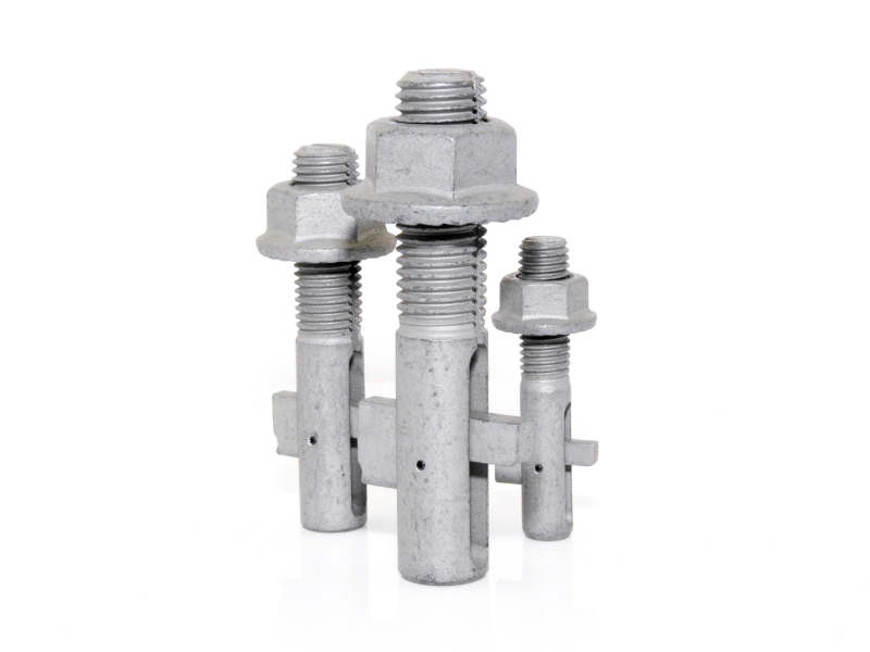
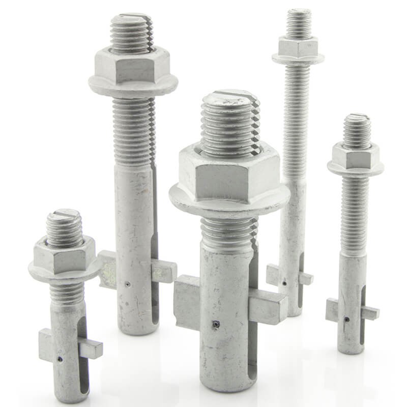
Blind Bolt
The Blind Bolt is so versatile that our clients are always coming up with new demands, new uses and different applications. We rise to the challenge, manufacturing additional sizes designed to save time and money.
ICC-ES Approved to AC437
The Blind Bolt Company has received confirmation from ICC Evaluation Service, LLC (ICC-ES), that The Blind Bolt complies with the provisions of the ESR-3617.
This confirmation, as evidence in ICC-ES evaluation report ESR-3617, provides guidance to code officials faced with approving the use of The Blind Bolt under these codes.
The evaluation report is available opposite
and online at www.icc-es.org.


Find Your Standard Blind Bolt
Input the overall thickness

Blind Bolt
Technical Data Explained
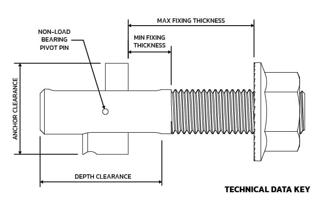
NOTE: All dimensions are in inches unless stated otherwise.
The Blind Bolt Company reserve the right to change these technical details without notice.
Blind Bolt Product Specification Zinc Flake 1000Hr SSP - Property Class 10.9 |
||||||||
| Bolt Size | Box | Hole | Fixing thickness | Anchor | Depth | Minimum | ||
| (Stock Number) | Qty | Diameter | Min | Max | Clearance | Clearance | Hole Centres | |
| M8 x 50 | 50 | 9 | 9 | 24 | 19 | 25 | 22 | |
| BB0850DTASM | 11⁄32" | 23⁄64" | 15⁄16" | 3⁄4" | 63⁄64" | 25⁄32" | ||
| M10 x 60 | 40 | 11 | 10 | 30 | 23 | 30 | 26 | |
| BB1060DTASM | 7⁄16" | 25⁄64" | 1 3⁄16" | 29⁄32" | 1 3⁄16" | 25⁄32" | ||
| M10 x95 | 20 | 11 | 25 | 65 | 23 | 30 | 26 | |
| BB1095DTASM | 7⁄16" | 63⁄64" | 2 9⁄16" | 29⁄32" | 1 3⁄16" | 25⁄32" | ||
| M10 x 130 | 20 | 11 | 55 | 100 | 23 | 30 | 26 | |
| BB10130DTASM | 7⁄16" | 2 11⁄64" | 3 15⁄16" | 29⁄32" | 1 3⁄16" | 25⁄32" | ||
| M12 x 70 | 20 | 13 | 12 | 35 | 26 | 35 | 32 | |
| BB1270DTASM | 1⁄2" | 15⁄32" | 1 3⁄8" | 1 1⁄32" | 1 3⁄8" | 63⁄64" | ||
| M12 x 120 | 25 | 13 | 30 | 85 | 26 | 35 | 32 | |
| BB12120DTASM | 1⁄2" | 1 2⁄16" | 3 11⁄32" | 1 1⁄32" | 1 3⁄8" | 63⁄64" | ||
| M12 x 180 | 20 | 13 | 80 | 140 | 26 | 35 | 32 | |
| BB12180DTASM | 1⁄2" | 3 5⁄32" | 5 23⁄64" | 1 1⁄32" | 1 3⁄8" | 63⁄64" | ||
| M14 x 75* | 20 | 14.5 | 14 | 35 | 32 | 38 | 36 | |
| GBB1475DTASM | 9/16" | 9/16" | 1 1/8" | 1 1/4" | 1 1/2" | 1 1/4" | ||
| M14 x 125* | 20 | 14.5 | 28 | 82 | 32 | 38 | 36 | |
| GBB14125DTASM | 9/16" | 1 1/8" | 3 1/4" | 1 1/4" | 1 1/2" | 1 1/4" | ||
| M14 x 185* | 20 | 14.5 | 75 | 142 | 32 | 38 | 36 | |
| GBB14185DTASM | 9/16" | 3" | 5 1/2" | 1 1/4" | 1 1/2" | 1 1/4" | ||
| M16 x 90* | 20 | 17 | 13 | 43 | 36 | 43 | 40 | |
| GBB1690DTASM | 11⁄16" | 33⁄64" | 1 11⁄64" | 1 27⁄64" | 1 11⁄16" | 1 3⁄8" | ||
| M16 x 130* | 15 | 17 | 40 | 75 | 36 | 43 | 40 | |
| GBB16130DTASM | 11⁄16" | 1 27⁄64" | 2 61⁄64" | 1 27⁄64" | 1 11⁄16" | 1 3⁄8" | ||
| M16 x 180* | 10 | 17 | 55 | 125 | 36 | 43 | 40 | |
| GBB16180DTASM | 11⁄16" | 2 11⁄64" | 4 59⁄64" | 1 27⁄64" | 1 11⁄16" | 1 3⁄8" | ||
| M20 x 110* | 10 | 22 | 21 | 56 | 44 | 56 | 48 | |
| GBB20110DTASM | 13⁄16" | 53⁄64" | 2 13⁄64" | 1 47⁄64" | 2 13⁄16" | 1 57⁄64" | ||
| M20 x 140* | 8 | 22 | 21 | 86 | 44 | 56 | 48 | |
| GBB20140DTASM | 13⁄16" | 53⁄64" | 3 25⁄64" | 1 47⁄64" | 2 13⁄64" | 1 57⁄64" | ||
| M20 x 180* | 10 | 22 | 80 | 120 | 44 | 56 | 48 | |
| GBB20180DTASM | 13⁄16" | 3 5⁄32" | 4 23⁄32" | 1 47⁄64" | 2 13⁄64" | 1 57⁄64" | ||
| M20 x 250* | 10 | 22 | 130 | 185 | 44 | 56 | 48 | |
| GBB20250DTASM | 13⁄16" | 5 1⁄8" | 7 9⁄32" | 1 47⁄64" | 2 13⁄64" | 1 57⁄64" | ||
| M24 x 130* | 5 | 26 | 21 | 66 | 53 | 64 | 58 | |
| GBB24130DTASM | 1 " | 53⁄64" | 2 19⁄32" | 2 3⁄32" | 2 33⁄64" | 2 23⁄64" | ||
| M30 x 140* | 5 | 32 | 27 | 60 | 65 | 72 | 74 | |
| GBB30140DTASM | 1 1⁄4" | 1 1⁄16" | 2 23⁄64" | 2 9⁄16" | 2 53⁄64" | 2 61⁄64" | ||
DESIGN RESISTANCES DETERMINED IN ACCORDANCE WITH AC 437 AND AISC 360-10 |
|||||||||||||
| Diameter inch (mm) |
Tensile Resistance | Shear Resistance Through Slot | Shear Resistance Through Unslotted Threaded Shank | Recommended Tightening Torque (lbf) | |||||||||
| LRFD | ASD | LRFD | ASD | LRDF | ASD | ||||||||
| kN | KIPS | kN | KIPS | kN | KIPS | kN | KIPS | kN | KIPS | kN | KIPS | ||
| 0.345 (8) | 6.8 | 1.53 | 4.2 | 0.94 | 5.8 | 1.30 | 3.6 | 0.81 | 17.0 | 3.82 | 11.3 | 2.54 | 11 |
| 0.394 (10) | 9.5 | 2.14 | 5.9 | 1.33 | 13.7 | 3.08 | 8.6 | 1.93 | 26.5 | 5.96 | 17.7 | 3.98 | 18 |
| 0.472 (12) | 15.1 | 3.39 | 9.4 | 2.11 | 17.8 | 4.00 | 11.1 | 2.50 | 38.2 | 8.59 | 25.4 | 5.71 | 22 |
| 0.551 (14) | 22.7 | 5.10 | 14.2 | 3.19 | 24.5 | 5.51 | 15.3 | 3.44 | 52.0 | 11.69 | 34.6 | 7.78 | 28 |
| 0.630 (16) | 28.4 | 6.38 | 17.8 | 4.00 | 30.7 | 6.90 | 19.2 | 4.32 | 67.9 | 15.26 | 45.2 | 10.16 | 36 |
| 0.787 (20) | 45.4 | 10.21 | 28.4 | 6.38 | 54.0 | 12.14 | 33.7 | 7.58 | 106.0 | 23.83 | 70.7 | 15.89 | 48 |
| 0.945 (24) | 75.4 | 16.95 | 46.5 | 10.45 | 75.7 | 17.02 | 47.3 | 10.63 | 152.7 | 34.33 | 101.8 | 22.89 | 55 |
| 1.181 (30) | 110.2 | 24.77 | 68.9 | 15.49 | 110.7 | 24.89 | 69.2 | 15.56 | 238.6 | 53.64 | 159.0 | 35.74 | 63 |
In bearing, the resistance of a blind bolt should satisfy the requirements of AISC specification 360-10 clause J3-10, expressions J3-6a or J3-6b as required, using the nominal diameter d, of the bolt. No reduction in diameter to allow for the slot is required.
In combined tension and shear, blind bolts should satisfy the following expressions:
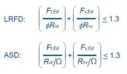
Ft,Ed and Fv,Ed are the applied tension and shear forces respectively (LRFD or ASD values) ØRnt and Rnt /Ω are the design tension resistance (LRFD or ASD), from the above table. ØRnv and Rnv /Ω are the design shear resistance (LRFD or ASD) from the above table. The above resistances and interaction criteria make no allowance for the deformation or yield of the connected part.
Important Note
The above tension resistances make no allowance for the deformation or yield of the connected parts. An appropriate design model for connections in hollow sections can be found in Joints and Steel Construction: Simple Connections.
Stainless Steel Blind Bolts Technical Data
Blind Bolt Product Specification Stainless Steel A4-70 |
||||||||
| Bolt Size | Box | Hole | Fixing thickness | Anchor | Depth | Minimum | ||
| (Stock Number) | Qty | Diameter | Min | Max | Clearance | Clearance | Hole Centres | |
| M8 x 50 | 50 | 9 | 9 | 24 | 19 | 25 | 22 | |
| BB0850A4ASM | 11⁄32" | 23⁄64" | 15⁄16" | 3⁄4" | 63⁄64" | 25⁄32" | ||
| M10 x 60 | 40 | 11 | 10 | 30 | 23 | 30 | 26 | |
| BB1060A4ASM | 7⁄16" | 25⁄64" | 1 3⁄16" | 29⁄32" | 3⁄16" | 25⁄32" | ||
| M12 x 90 | 20 | 13 | 12 | 55 | 26 | 35 | 32 | |
| BB1290A4ASM | 1⁄2" | 15⁄32" | 2 11⁄64" | 1 1⁄32" | 1 3⁄8" | 63⁄64" | ||
| M16 x 100* | 20 | 17 | 13 | 53 | 36 | 43 | 40 | |
| GBB16100A4ASM | 11⁄16" | 33⁄64" | 2 3⁄64" | 1 27⁄64" | 1 11⁄16" | 1 3⁄8" | ||
DESIGN RESISTANCES DETERMINED IN ACCORDANCE WITH AC 437 AND AISC DESIGN GUIDE 27 |
|||||||||||||
| Diameter inch (mm) |
Tensile Resistance | Shear Resistance Through Slot |
Shear Resistance Through Unslotted Threaded Shank |
Recommended Tightening Torque (lbf) | |||||||||
| LRFD | ASD | LRFD | ASD | LRFD | ASD | ||||||||
| kN | KIPS | kN | KIPS | kN | KIPS | kN | KIPS | kN | KIPS | kN | KIPS | ||
| 0.345 (8) | 3.9 | 0.88 | 2.4 | 0.54 | 6.7 | 1.51 | 4.5 | 1.01 | 11.9 | 2.68 | 7.9 | 1.78 | 11 |
| 0.394 (10) | 9.2 | 2.07 | 5.8 | 1.30 | 11.4 | 2.56 | 7.6 | 1.71 | 18.6 | 4.18 | 12.4 | 2.79 | 16 |
| 0.472 (12) | 14.4 | 3.24 | 9.0 | 2.02 | 15.9 | 3.57 | 10.6 | 2.38 | 26.7 | 6.00 | 17.8 | 4.00 | 20 |
| 0.630 (16) | 31.0 | 6.97 | 19.4 | 4.36 | 31.0 | 6.97 | 20.6 | 4.63 | 47.5 | 10.68 | 31.7 | 7.13 | 33 |
For bearing in carbon steel elements, the resistance of a stainless steel blind bolt should satisfy the requirements of AISC specification 360-10 clause J3-10, expressions J3-6a or J3-6b as required, using the nominal diameter d, of the bolt. No reduction in diameter to allow for the slot is required.
The bolt should satisfy the requirements of AISC Design Guide 27, section 9.3.6, expressions 9-1 or 9-4 as required, using the nominal diameter d, of the bolt. No reduction in diameter to allow for the slot is required. It may be assumed that for the common grade of austenitic stainless steel, Fu = 515 N/mm2 (75 ksi).
In combined tension and shear, stainless steel blind bolts should satisfy the following expressions:
Ft,Ed and Fv,Ed are the applied tension and shear forces respectively (LRFD or ASD values) ØRnt and Rnt /Ω are the design tension resistance (LRFD or ASD), from the above table.ØRnv and Rnv /Ω are the design shear resistance (LRFD or ASD) from the above table. The above resistances and interaction criteria make no allowance for the deformation or yield of the connected part.
Important Note
The above resistances and interaction criteria make no allowance for the deformation or yield of the connected part.
Blind Bolt
Testing Data Explained
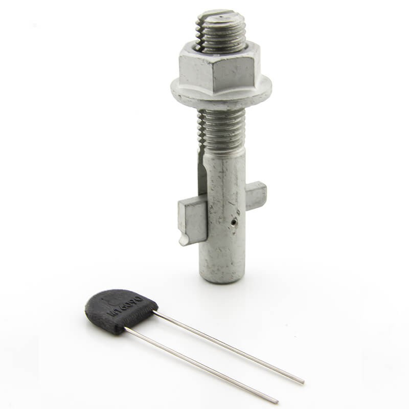
The versatility of the Blind Bolt design means that there are numerous fixing combinations possible in any given scenario. This leads to variation in the measured strength of each Blind Bolt thanks to the testing data. The tensile strength of the Blind Bolt remains the same no matter how it is used, but the shear strength is dictated by the thickness of the actual substance being clamped.
An overview of these variations is set out below and more detail can be found in our technical data sheets. These sheets can be accessed via the menu at the top of the page.
If you still have any questions about our testing data, please get in touch with us using the contact details at the bottom of the page or by sending us an email by clicking here.
Blind Bolt
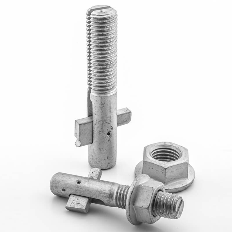
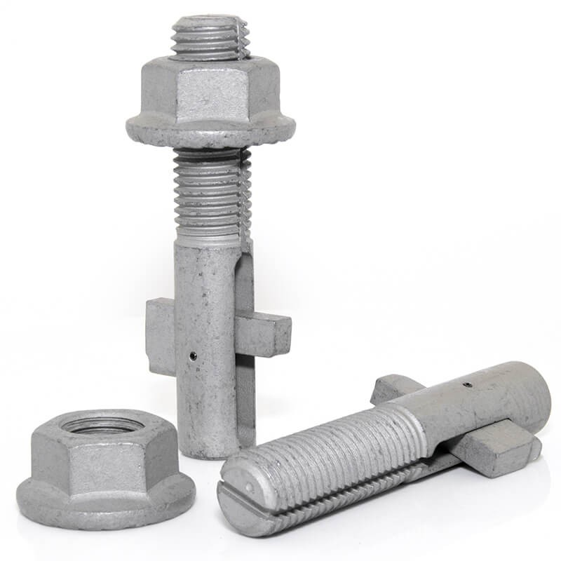
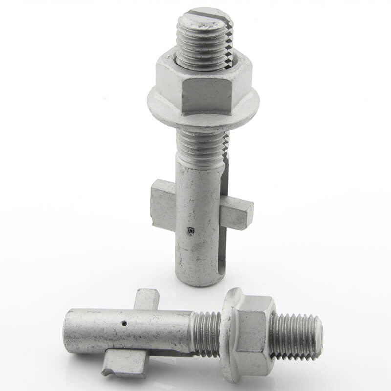
Fixing Data Explained
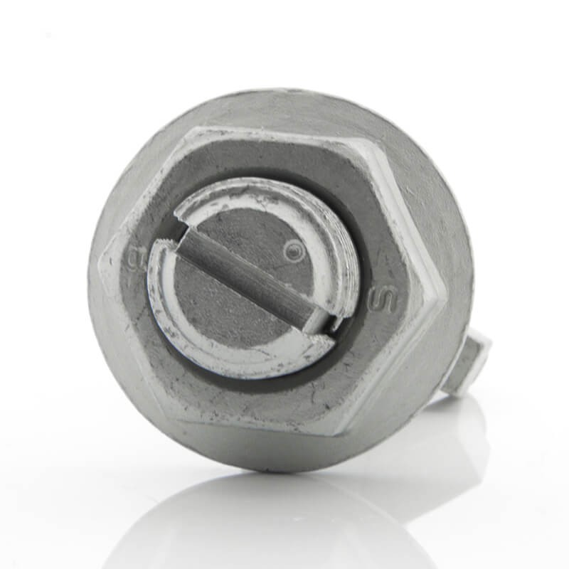
The unique and innovative design of the Blind Bolt means that certain specific criteria need to be met in order for it to be applied successfully. Using these criteria means being aware of the way in which the dimensions of each bolt are measured, and these details are set out below.
The image above also offers a pictorial representation of each term.
If you still have any questions, please get in touch with us using the contact details at the bottom of the page or by sending us an email by clicking here.
Blind Bolt
Fitting Instructions
Installations & Removal Videos
The following videos visually represent both the detailed installation and removal of the Blind Bolt.
Blind Bolt
Horizontal Installation

Blind Bolt
Horizontal Removal

Blind Bolt Downward Installation

Blind Bolt Vertical Removal

Blind Bolt Fitting Instructions (PDF Download)
Blind Bolt
SCI Report
